DOMINANT
:
|
|
| Update record: | |||||||||||||||||
| 20070614 | DOMINANT calibration using GDOM calibration page uploaded | ||||||||||||||||
| |||||||||||||||||
 |
 |
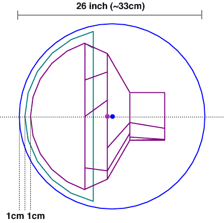
(fig.1 schematic side view of DOMINANT [pdf])
|
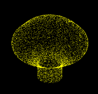
(fig.2 actual shape of the PMT [tiff])
|
[top]
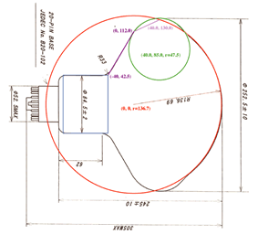
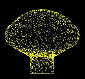
In order to obtain actual hit point of photons at PMT photo cathode, we constructed geometrical shape of PMT as one of the G4VSolid. Because our PMT shape is represented by some combination of Constructive Solid Geometry (CSG) Solids, we used G4UnionSolid to construct PMT.
 |
 |
(fig.3 parameter : [large
picture] [pdf])
|
(fig.4 side view of the PMT [tiff])
|
[top]
The DOMINANT requires absorption length and refractive index for all materials. Elisa Resconi measured the penetration ratios of glass and gel. We calculated the absorption length from her data.
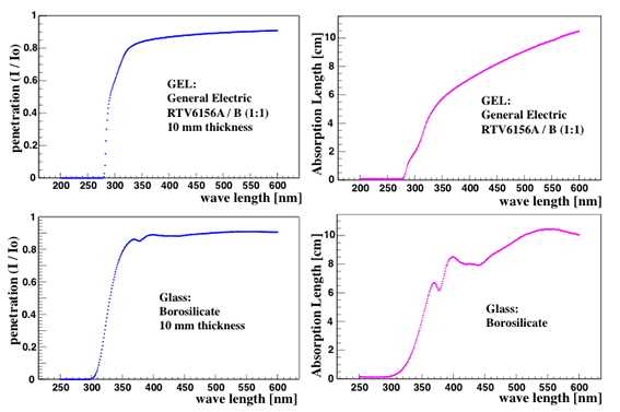
[penet_glass.pdf] [penet_gel.pdf] [absorp_glass.pdf] [absorp_gel.pdf]
[top]
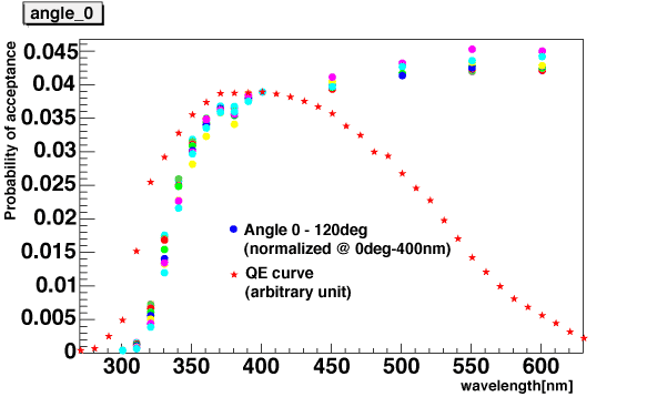
Using the DOMINANT, we generated acceptance table for our 13inch DOM. Because the Photonics calculates an amplitude / 1m^2, the photon beam is injected to the DOM from 1m^2 beam spot with an off-axis angle theta. The acceptances as a function of wavelength and off-axis angle are obtained as follows.
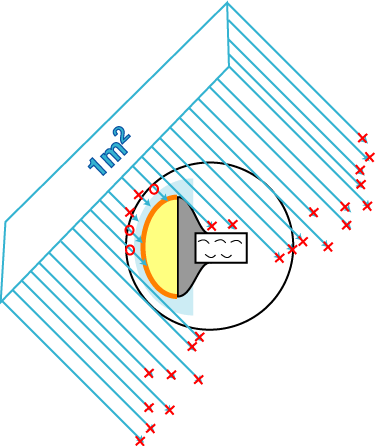 [pdf] [pdf] |
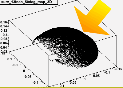 [tiff] [tiff] |
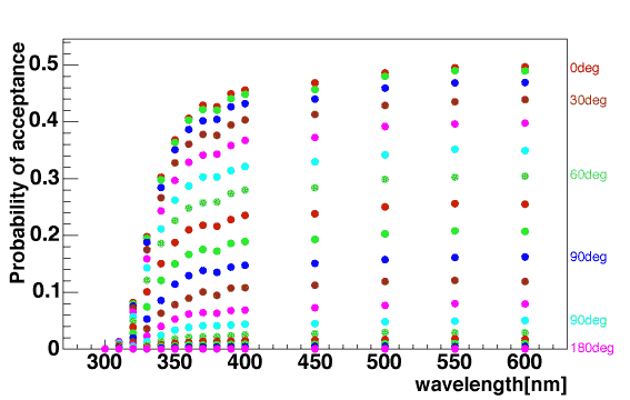
[pdf]
The colors of spots indicates off-axis angle, angle between beam direction and PMT axis. 0 degree means beam injected from top of the photo-cathode of PMT. Taking a careful look of the figure, each shape of acceptance curve looks similar. It may be good approximation to separate these two variables, wavelength and off-axis angle, as follows:
| final_acceptance(theta, lambda)
= angle_acceptance(theta) * wavelength_acceptance(lambda) |
within all range of our assuming wavelength.
This expression indicates that we can regard the angle_acceptance(theta)
as a normalization factor of wavelength_acceptance(lambda) curve and
the highest normalization factor should be 1 at the off-axis angle
theta = 0 deg.
We decided to generate two 1-dimensional tables about wavelength and
acceptance for DOM, instead of one 2-dimensional convoluted acceptance
table. The ROMEO, fast ROOT based OM simulator, is also using these two
tables.
[top]
The wavelength_acceptance is defined as follows
| Number of photons arrived at
PMT surface(lambda)/ Number of photons injected to DOM from 1m^2 photon source(lambda) |
at off-axis angle theta = 0.
The
acceptance of photons as a function of wavelength at theta =
0 (text file)
ATTENTION!!! The table does not
include reflection and reflaction process, only affected
by absourption process.
[pdf]
[top]
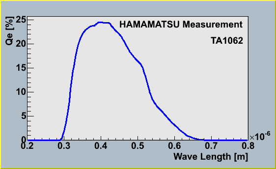
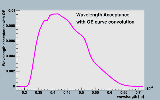
Convoluting the acceptance table and QE curve, we can get acceptance of photo-electrons as a function of wavelength. This table would be used by AMANDA simulator.
[eps]
The acceptance of photo-electrons is calculated by
Number of photons arrived
at PMT surface(lambda) * QE(lambda) / |
The
acceptance of photo-electrons as a function of wavelength at
theta = 0 (text file)
ATTENTION!!! The table does not include
reflection and reflaction process, only affected by absourption
process.
[pdf]
[top]
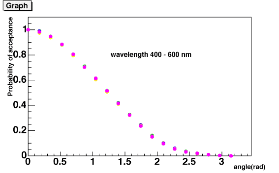
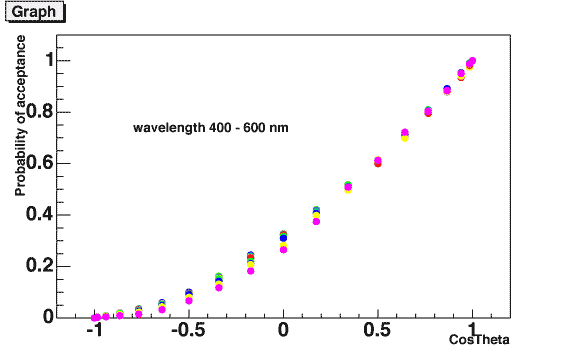
The angle acceptance is calculated by
| acceptance_at_theta / acceptance_at_0degree |
as a function of injection angle theta (at DOM local coordinate) and
cos(theta).
Both functions are fitted by polynomial functions, the former is represented
by pol(5) and the latter is pol(2). The ROMEO is using these fitting
functions.
[top]
| Photon Propagator (Toy Monte-Carlo) |
Ray trace&BG sim (DOMINANT) |
PMT Handy c++ sim (ROMEO) |
Back to the Chiba Icecube Home |