Preparing the Laboratory
Before inserting the D-Eggs into the freezer, ensure the laboratory is in a state ready for FAT testing. It is important for everyone to perform these checks to ensure there are no problems since the last FAT was run. Refer to the previous sections about preparing the laboratory for more details on operating the hardware including the concept of the jumper box and mini-fieldhub (MFH).
Inspect the jumper boxes and MFHs for loose cables
Confirm the thermometer and humidity sensors are operational
Check that the
icehap-daqmachine has at least 100 GB of free disk space remaining.Make sure the air conditioning/climate control is set to a reasonable temperature for the given season.
You can confirm the operations of the monitoring software by checking the #chiba-daq Slack channel.
New plots are sent to the channel every few hours.
To reduce humidity inside the laboratory, climate control should be constantly in operation. Please make sure this is enabled to a reasonable temperature.
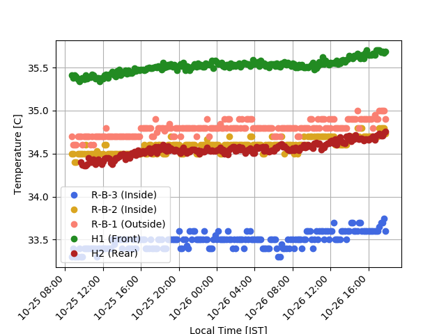
Inside the freezer are 5 independent temperature sensors: 2 from the humidity sensors (H1 and H2) and 3 thermalcouples (R-B-X). One humidity sensor is located near the door and air-exchange (H1), the other is located in the back, away from the cable feed-throughs (H2). The thermalcouples are all located close to the cable feed-throughs. R-T-2 and R-T-3 are attached to the interior roof of 2 D-Egg boxes. R-T-1 is attached to the exterior roof of the D-Egg box.
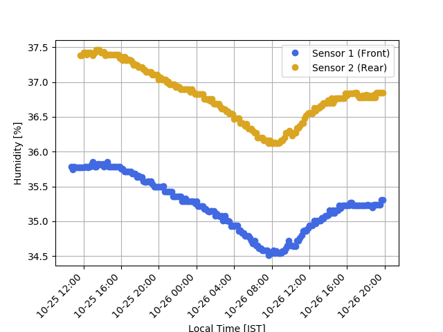
Humidity is monitored with the two humidity sensors described above. The humidity has not yet been monitored during cold cycles and should be followed closely.
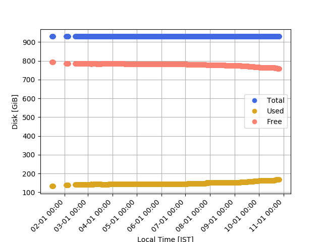
Disk usage detailing total, used, and free space. Automated warning are set to alert slack when free space decreases below 50 GB, however shifters should ensure at-least 100 GB before FAT start. Values will be modified as the FAT is refined.
Freezer Ramp
Sometimes also referred to as the ‘slope’, the freezer ramp is used to easily access the freezer and insert/remove D-Eggs or other equipment. The ramp is composed of 4 components, two of which should already be attached and located outside the freezer. The third component should be placed with the white plastic feet inside the metal support tray surrounding the freezer with the end of the component resting on the freezer door frame. This piece is heavy and should be carried by at least 2 people. Once in place, engage the locks. Then insert the smaller 4th piece and also engage the locks.
Freezer Inspection
Before inserting D-Eggs, perform a visual inspection of the freezer. Look for potential damage to cables, fibres, boxes, or the shelves. Where possible, perform repairs. If a simple repair is not possible, contact the shifting leaders.
After warming up, the components inside the freezer are typically wet. Install the dehumidifiers inside the freezer and keep them operating for up to 48 hours. Remove any large amounts of water located on the equipment. Also in the case that signifiant water has accumulated on the freezer floor, take a little time to remove some. This is most easily done with some pieces of cloth that can be found in the freezer lab.
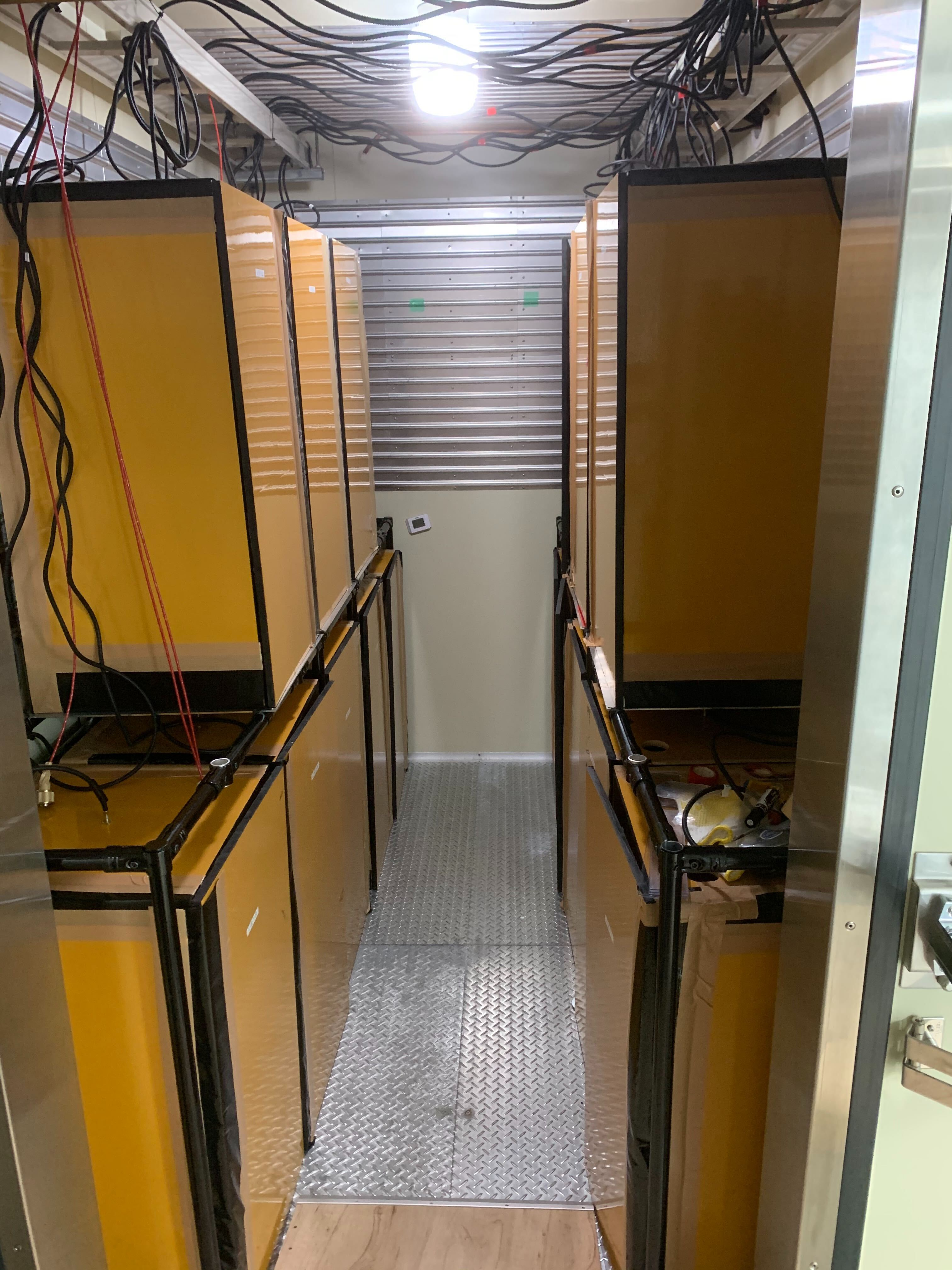
Another inspection should be performed before turning on the freezer. Remember to document freezer access using the FAT Logbook ‘Freezer Access’ form.
Note About Naming Scheme
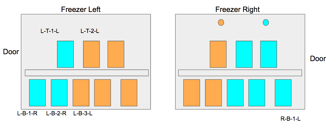
This shows the box naming scheme inside the freezer.
The naming scheme is straightforward:
First letter indicates the side of the freezer: (L)eft or (R)ight.
Second letter indicates the height: (B)ottom or (T)op.
The third is a number, starting to count from the freezer door.
Last is the letter indicating the side the door opens from.
The last letter is only indicated on the box itself. Looking at the jumper box labeling, you would notice that only the first two letters and the number are used. Additionally if you look at the labelling for the optical fibres, they use the same first two letters and number, however the last letter is different. This helps us differentiate between the (T)op and (B)ottom fibres.
Installing D-Eggs
Before you install any D-Eggs, be sure you have received training as it is easy to damage fragile components. As you are installing the D-Eggs, record the information in the FAT Logbook.
Have one person stand inside the freezer, ready to receive the D-Eggs.
This person should prepare the box by opening the door and carefully moving the communications cable to the top of the box. This cable is fragile!
Wheel D-Eggs up the ramp and into the freezer. Take care of the metal piece at the end of the ramp.
Insert the D-Egg into the box, with the lock-able wheels facing outwards and the PCA to the left side.
If this is on the top row, using two people, very carefully lift the D-Egg into the box. Secure the wheel locks.
Carefully connect the PCA to the comm. cable. Do not put pressure on the exposed wires. Instead apply a small amount of pressure from the hard rubber back-shell. This is to ensure contact between the pins and the PCA.
Proceed to insert all D-Eggs into their testing boxes. The final two boxes L-B-1-R and R-B-1-L require the small ramp piece to be removed. Insert these D-Eggs into the freezer, remove the ramp, then insert the D-Eggs into the testing boxes.
Testing Connections
It is important to perform connections tests once all D-Eggs have been inserted into the freezer. This is because broken connections with addressing wires could cause one D-Egg to appear on another port, interferring with communications. The most common issues observed during this testing period relate to three specific ways the comm. cables can break, which will be covered later.
As before when determining the ICM ID and flashID for the D-Egg, we’ll make use of DomNet and telnet.
Current jumper box design distributes 4 D-Eggs across each ICM, meaning a single run of icm_probe should return 5 ICMs: 4 D-Eggs and the MFH ICM.
These channels have been setup such that the D-Eggs should appear on channels 0 to 3.
You can check which D-Egg should be on which channel based on the comm. cable label.
It might be useful to verify manually the D-Egg ICM ID, channel, and box to ensure no instances of channels “swapping” occurs.
Before running icm_probe start a doment session for the given set of D-Eggs.
Repeat the icm_probe test for all 4 MFH ICMs.
Once connection is established with all D-Eggs, finish sealing the boxes with tape.
If any D-Eggs do not immediately display, attempt the icm_probe a few more times. Sometimes D-Eggs can be in a boot routine and are not yet ready to respond.
Consider rebooting the MFHs once to try again.
If D-Eggs continue to be unrepsonsive or channels 4 to 7 are populated, this is likely due to a cable failure.
Commonly cable failures occur at the penetrator cable assembly end (inside the freezer).
D-Eggs appearing on channels 4 to 6 most likely have 1 or more addressing wires loose or disconnected. Appearing on channel 7 indiciates that most or all addressing wires are loose or disconnected. Failure to be identified could simply mean that the pins in the PCA are not sufficiently connected. However a lack of connection could also mean that one or both of the power wires are loose or disconnected.
Debugging Connections
Of course, before adjusting any cables, disable power to the mini-fieldhubs.
Before disassembling any cables, the easiest debugging approach is to assume that the PCA is not well-connected. Very carefully remove the comm. cable and examine if the inner plastic piece has been pushed into the metal housing. Gently adjust the inner plastic piece to be flush with the metal housing. If necessary, use tape to secure it in place. Attempt any connections again.
D-Eggs which remain unresponsive will need further inspection. Disconnect the PCA and begin to carefully remove the tape around the connector. Remove the plastic insert from the metal housing. Consider using a multimeter and the long orange wire to test connectivity between the pins. Delicately examine each individual connection. If needed separate the two plastic pieces, and test the pins. At this point it should be obvious if any wires are loose or damaged.
Repairing Connections
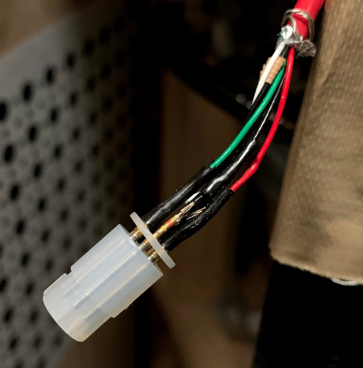
Here you can see a sample broken cable, where the wire has become disconnected from the metal pin.
Repairing the connections can be challenging as it requires considerable soldering skills. Before proceeding with any repair, contact the shifting leaders.
To perform the most common type of repair, the broken wire is extended with another smaller wire. This wire is then soldered to both the connector pin and the broken wire end. When soldering inside the freezer, follow these steps:
Disconnect any optical fibres that may be near-by to prevent damage.
Disconnect the Dsub-9 end of the cable from the jumper box, due to heat transfer along wires.
Solder fumes are unsafe, leave the door to the freezer open and install a fan.
Use proper lighting - working inside the freezer can be dark.
Test the connections with the multi-meter once repairs have finished. This is most easily handled by an “extension” wire to the multi-meter pins.